

Kit Includes:
1. Start by killing the electricity to the signal. You do not need to remove any signals from your layout to do the installation if your wiring is located under the layout. Find the bundle of wires (usually 3) that runs between the signal and your signal controller. In an area of those wires that contains slack, snip them apart and strip the six new ends you have created.
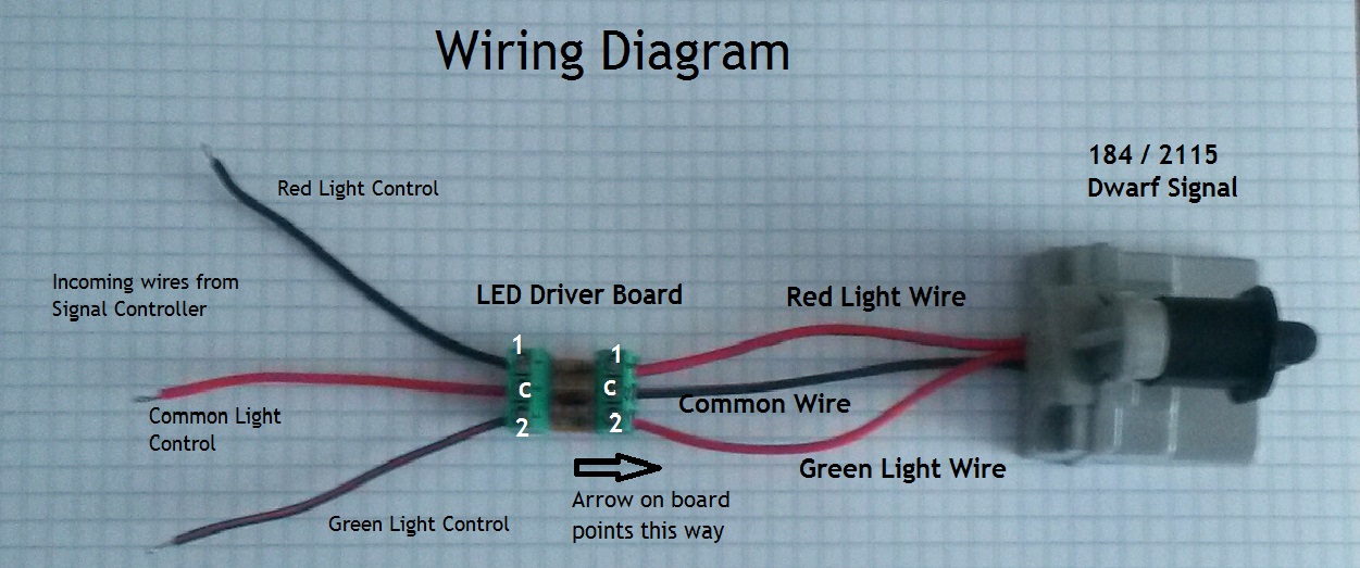
2. Familiarize yourself with the power reduction board. It has two 3-block terminals; one on each end labeled 1, C, 2. C is the common terminal. 1 is for the red light, 2 is for the green light. Also note the arrow on the side of one terminal block. This arrow points towards the signal, thus the wires to the signal will be attached here.
3. Paying close attention the picture diagram above, wire the power reduction board between the two newly created bundles of 3 wires. The arrow points toward the signal. Incoming wires from the controller wire to the opposite end. To attach the wires, simply loosen the terminal screws on the block, insert the wire under the tab, and retighten the terminal screws.
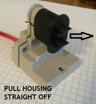
4. Time to install the LED's. Start by removing the black housing covering the light bulbs. Simply pull the housing straight off. This is true for all versions of this signal
5. Remove the bulbs from the sockets. Gently pull the original bulbs straight out. Springs hold the 2-pin bulbs in place.
6. Re-insert the new LED "bulbs" into the signal sockets. Gently squeeze the prongs for the LEDs and slide them into the opening. You should feel some pressure as the springs grab the prongs. This should be a snug fit.
7. It's time to check the wiring. Re-apply power to the signal. Determine which color is supposed to be lit right now. Let's say green for sake of argument. The green LED should be lit. If not: TWO THINGS COULD BE HAPPENING:
(1.) The LED may be in backwards. LEDs require correct polarity to operate. Remove the green LED "Bulb" and insert it the opposite way. Does it light now? If not check the next option.
(2.) Is the red LED on? It may be trying to light but is also in backwards. Remove the red LED and insert it in the opposite direction. Does it light now? If so, the number 1 and number 2 terminal wires of the power reduction board to the signal are backwards. Simply reverse those two wires and the green LED should come on. If the green still won't come on, try option 1 again, you may have had it correct the first time and reversed it during trouble shooting.
THIS MAY SEEM CONFUSING BUT TAKE YOUR TIME AND THINK IT THROUGH CAREFULLY. THERE IS ONLY TWO THINGS THAT CAN BE WRONG. 1. LED IS IN BACKWARDS or 2. THE HOOK UP WIRES ARE BACKWARDS. IT'S A TRIAL AND ERROR PROCESS. BUT YOU'LL LOVE THE END RESULT!
8. Once you're sure you have the wiring correct and the LEDs work properly, re-install the housing. Just push it over the sockets until the metal retaining clip latches into place. ENJOY YOUR MAINTENANCE FREE SIGNAL!!!
Where do you want to go next?
Back to Product Selection Page
 STEP 4
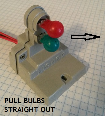 STEP 5
 STEP 6