

Specifications
1. Start by removing the shell of the locomotive from the chassis. This is done by removing 4 phillips head screws located under the locomotive. Please note the locations in the picture.
2. Once the shell has been separated, we need to drill out the firebox door. Using a 5/16" or similar sized metal drill bit, carefully and slowly drill out the firebox door. This is a thick shell and you must proceed slowly to avoid major damage to your locomotive. I recommend using a slow speed and a newer bit designed to drill through metal.
3. This step is optional. You may place the white dot diffuser on the inside of the shell covering the hole you just drilled. This diffuser helps distribute the light from the LED and creates a more realistic glow. Again, this is not necessary or you may wish to use another type of material to act as a diffuser. Be sure the hole is covered completely.
4. Next, remove the green paper from the back of the adhesive foam on the circuit board. Be careful not to touch the adhesive, it will reduce the sticking ability. Carefully line up the LED so it is located directly behind the drilled hole. The LED should be between 1/8"and 1/4" behind the diffuser dot. At this point you may wish to take a 9v battery and illuminate the circuit to see how the LED looks from the cab. Some movement and careful positioning may be required to get the desired look. Once you have the perfect spot, press the circuit gently against the shell and hold for 30 seconds to secure it.
5. To wire the circuit, the pigtails will be soldered to the headlight at the front of the locomotive. This is the safest spot to tap into power. Add a small gob of solder to the corner of the headlight plate as seen in the picture. Then carefully solder the black pigtail to the gob of solder.
6. Solder the red wire to the tip of the base of the light bulb socket. Be sure the power wire to the headlight does not pop off when connecting the firebox circuit.
7. Now gently feed the wire along the inside of the locomotive and place the shell back onto the chassis without the screws. Place the locomotive on the rails and apply power. If the circuit illuminates and you are happy with the look, reattach the four screws and enjoy! If the circuit does not light, check for loose wires, dislodged wires, or crimped wires.
Where do you want to go next?
Back to Product Selection Page
 STEP 1
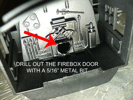 STEP 2
 STEP 3
 STEP 4
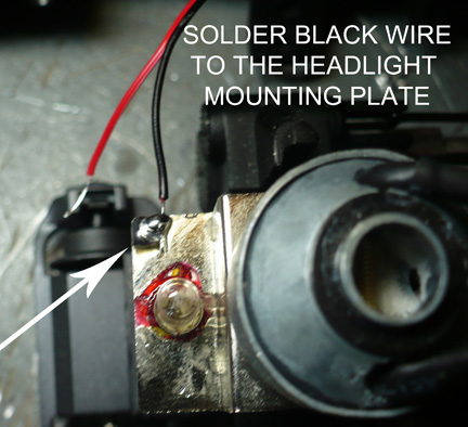 STEP 5
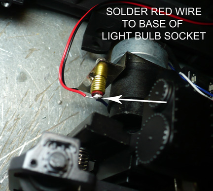 STEP 6
 STEP 7